IN MEMORIAM
“The future is not free: the story of all human progress is one of a struggle against all odds. We learned again that this America, which Abraham Lincoln called the last, best hope of man on Earth, was built on heroism and noble sacrifice. It was built by men and women like our seven star voyagers, who answered a call beyond duty, who gave more than was expected or required and who gave it little thought of worldly reward.”
– President Ronald Reagan January 31, 1986
Francis R. (Dick) Scobee, Commander, Career Astronaut
Michael John Smith, Pilot, USN Captain
Ellison S. Onizuka, Mission Specialist One, USAF Lt. Colonel
Judith Arlene Resnik, Mission Specialist Two, Career Astronaut
Ronald Erwin McNair, Mission Specialist Three, Career Astronaut
S.Christa McAuliffe, Payload Specialist One, Teacher
Gregory Bruce Jarvis, Payload Specialist Two
The launch of mission 51-L was postponed three times. the Challenger countdown was rescheduled for January 28.
The weather was forecast to be clear and very cold, with temperatures dropping into the low twenties overnight. The management team directed engineers to assess the possible effects of temperature on the launch. No critical issues were identified to management officials, and while evaluation continued, it was decided to proceed with the countdown and the fueling of the External Tank.
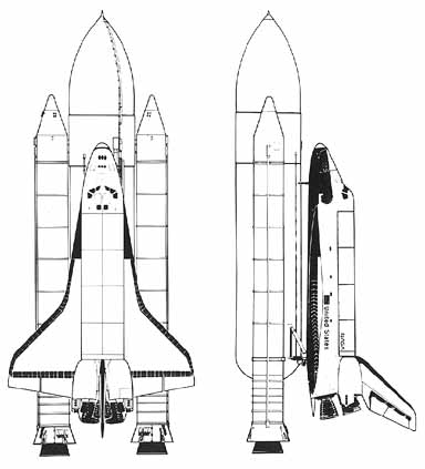
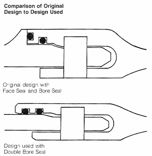
(NASA drawing of Space Ship Challenger)
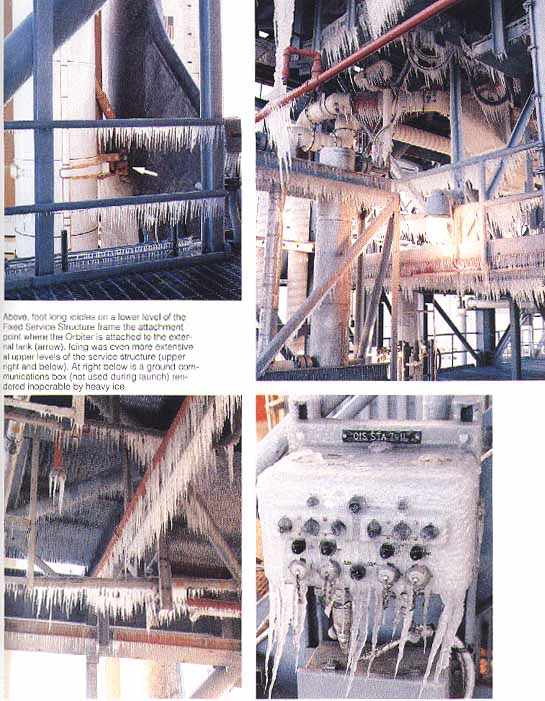
Ice had accumulated in the launch pad area during the night and it caused considerable concern for the launch team. In reaction, the ice inspection team was sent to the launch pad at 01:35 a.m., January 28, and returned to the Launch Control Center at 03:00 a.m. After a meeting to consider the team’s report, the Space Shuttle program manager decided to continue the countdown. Another ice inspection was scheduled at launch minus three hours.
Also, during the night, prior to fueling, a problem developed with a fire detector in the ground liquid hydrogen storage tank. Though it was ultimately tracked to a hardware fault and repaired, fueling was delayed by two and one-half hours. By continuing past a planned hold at launch minus three hours, however, the launch delay was reduced to one hour. Crew wake-up was rescheduled for 06:18 a.m., January 28, but by that time the crew was already up.
Because of forecast rain and low ceilings at Casablanca, the alternate abort site, that site was declared a “no-go” at 07:30 a.m. The change had no mission impact, however, because the weather at the primary transatlantic abort landing site at Dakar, Senegal, was acceptable. The abort-once-around site was Edwards Air Force Base, California.
With an extra hour, the crew had more than sufficient time to eat breakfast, get a weather briefing and put on flight gear. At the weather briefing, the temperature and ice on the pad were discussed, but neither then nor in earlier weather discussions was the crew told of any concern about the effects of low temperature on the Shuttle System. The seven crew members left the crew quarters and rode the astronaut van to launch pad B, arriving at 08:03. They were in their seats in the Challenger at 08:36 a.m.
At 08:44 a.m. the ice team completed its second inspection. After hearing the team’s report, the program manager decided to allow additional time for ice to melt on the pad. He also decided to send the ice team to perform one final ice assessment at launch minus 20 minutes. When the count was resumed, launch had been delayed a second hour beyond the original lift off time of 09:38 a.m., Eastern Standard Time.
At 11: 15 the ice inspection was completed, and during the hold at launch minus nine minutes, the mission 51-L crew and all members of the launch team gave their “go” for launch. The final flight of the Challenger began at 11:38:00.010 a.m., Eastern Standard Time, January 28, 1986.

(Space Ship Challenger, Morning of the launch)
The Flight of the Challenger
The events that followed lift off were brief:
Launch Time Event
– 6.6 sec. Space Shuttle engines ignition
0 sec. Solid Rocket Booster ignition
+ 7 sec. “Roll program.” (Challenger)
“Roger, roll, Challenger.” (Houston)
+ 24 sec. Main engines throttled down to 94%
+ 42 sec. Main engines throttled down to 65%
+ 59 sec. Main engines throttled up to 104%
+ 65 sec. “Challenger, go at throttle up.” (Houston)
“Roger. Go at throttle up.” (Challenger)
+ 73 sec. Loss of signal from Challenger
Findings
1. A combustion gas leak through the right Solid Rocket Motor aft field joint initiated at or shortly after ignition eventually weakened and/or penetrated the External Tank initiating vehicle structural breakup and loss of the Space Shuttle Challenger during STS Mission 51-L.
2. The evidence shows that no other STS 51-L Shuttle element or the payload contributed to the causes of the right Solid Rocket Motor aft field joint combustion gas leak. Sabotage was not a factor.
3. Evidence examined in the review of Space Shuttle material, manufacturing, assembly, quality control, and processing of nonconformance reports found no flight hardware shipped to the launch site that fell outside the limits of Shuttle design specifications.
4. Launch site activities, including assembly and preparation, from receipt of the flight hardware to launch were generally in accord with established procedures and were not considered a factor in the accident.
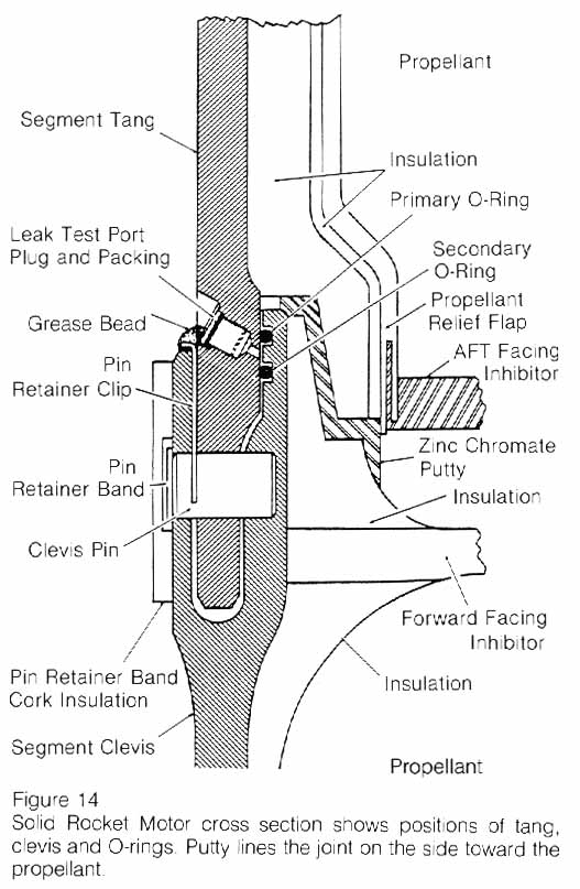
5. Launch site records show that the right Solid Rocket Motor segments were assembled using approved procedures. However, significant out-of-round conditions existed between the two segments joined at the right Solid Rocket Motor aft field joint (the joint that failed).
a. While the assembly conditions had the potential of generating debris or damage that could cause O-ring seal failure, these were not considered factors in this accident.
b. The diameters of the two Solid Rocket Motor segments had grown as a result of prior use.
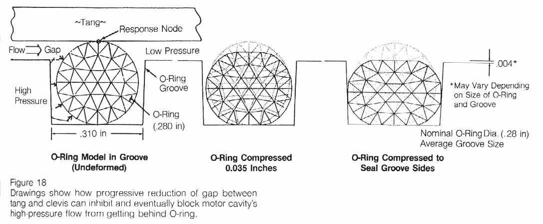
c. The growth resulted in a condition at time of launch wherein the maximum gap between the tang and clevis in the region of the joint’s O-rings was no more than .008 inches and the average gap would have been .004 inches.
d. With a tang-to-clevis gap of .004 inches, the O-ring in the joint would be compressed to the extent that it pressed against all three walls of the O-ring retaining channel.
e. The lack of roundness of the segments was such that the smallest tang-to-clevis clearance occurred at the initiation of the assembly operation at positions of 120 degrees and 300 degrees around the circumference of the aft field joint. It is uncertain if this tight condition and the resultant greater compression of the O-rings at these points persisted to the time of launch. 6. The ambient temperature at time of launch was 36 degrees Fahrenheit, or 15 degrees lower than the next coldest previous launch.
a. The temperature at the 300 degree position on the right aft field joint circumference was estimated to be 28 degrees +/- 5 degrees Fahrenheit. This was the coldest point on the joint.
b. Temperature on the opposite side of the right Solid Rocket Booster facing the sun was estimated to be about 50 degrees Fahrenheit.
7. Other joints on the left and right Solid Rocket Boosters experienced similar combinations of tang-to-clevis gap clearance and temperature. It is not known whether these joints experienced distress during the flight of 51-L.
8. Experimental evidence indicates that due to several effects associated with the Solid Rocket Booster’s ignition and combustion pressures and associated vehicle motions, the gap between the tang and the clevis will open as much as .017 and .029 inches at the secondary and primary O-rings, respectively.
a. This opening begins upon ignition, reaches its maximum rate of opening at about 200-300 milliseconds, and is essentially complete at 600 milliseconds when the Solid Rocket Booster reaches its operating pressure.
b. The External Tank and right Solid Rocket Booster are connected by several struts, including one at 310 degrees near the aft field joint that failed. This strut’s effect on the joint dynamics is to enhance the opening of the gap between the tang and clevis by about 10-20 percent in the region of 300-320 degrees.
9. O-ring resiliency is directly related to its temperature.
a. A warm O-ring that has been compressed will return to its original shape much quicker than will a cold O-ring when compression is relieved. Thus, a warm O-ring will follow the opening of the tang-to-clevis gap. A cold O-ring may not.
b. A compressed O-ring at 75 degrees Fahrenheit is five times more responsive in returning to its uncompressed shape than a cold O-ring at 30 degrees Fahrenheit.
c. As a result it is probable that the O-rings in the right solid booster aft field joint were not following the opening of the gap between the tang and clevis at time of ignition.
10. Experiments indicate that the primary mechanism that actuates O-ring sealing is the application of gas pressure to the upstream (high-pressure) side of the O-ring as it sits in its groove or channel.
a. For this pressure actuation to work most effectively, a space between the O-ring and its upstream channel wall should exist during pressurization.
b. A tang-to-clevis gap of .O04 inches, as probably existed in the failed joint, would have initially compressed the O-ring to the degree that no clearance existed between the O-ring and its upstream channel wall and the other two surfaces of the channel.
c. At the cold launch temperature experienced, the O-ring would be very slow in returning to its normal rounded shape. It would not follow the opening of the tang-to-clevis gap. It would remain in its compressed position in the O-ring channel and not provide a space between itself and the upstream channel wall. Thus, it is probable the O-ring would not be pressure actuated to seal the gap in time to preclude joint failure due to blow-by and erosion from hot combustion gases.
11. The sealing characteristics of the Solid Rocket Booster O-rings are enhanced by timely application of motor pressure.
a. Ideally, motor pressure should be applied to actuate the O-ring and seal the joint prior to significant opening of the tang-to-clevis gap (100 to 200 milliseconds after motor ignition).
b. Experimental evidence indicates that temperature, humidity and other variables in the putty compound used to seal the joint can delay pressure application to the joint by 500 milliseconds or more.
c. This delay in pressure could be a factor in initial joint failure.
12. Of 21 launches with ambient temperatures of 61 degrees Fahrenheit or greater, only four showed signs of O-ring thermal distress; i.e., erosion or blow-by and soot. Each of the launches below 61. degrees Fahrenheit resulted in one or more O-rings showing signs of thermal distress.
a. Of these improper joint sealing actions, one-half occurred in the aft field joints, 20 percent in the center field joints, and 30 percent in the upper field joints. The division between left and right Solid Rocket Boosters was roughly equal. Each instance of thermal O-ring distress was accompanied by a leak path in the insulating putty. The leak path connects the rocket’s combustion chamber with the O-ring region of the tang and clevis. Joints that actuated without incident may also have had these leak paths.
13. There is a possibility that there was water in the clevis of the STS 51-L joints since water was found in the STS-9 joints during a destack operation after exposure to less rainfall than STS 51-L. At time of launch, it was cold enough that water present in the joint would freeze. Tests show that ice in the joint can inhibit proper secondary seal performance.
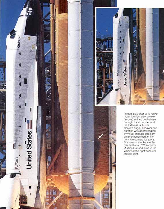
14. A series of puffs of smoke were observed emanating from the 51-L aft field joint area of the right Solid Rocket Booster between 0.678 and 2.500 seconds after ignition of the Shuttle Solid Rocket Motors.
a. The puffs appeared at a frequency of about three puffs per second. This roughly matches the natural structural frequency of the solids at lift off and is reflected in slight cyclic changes of the tang-to-clevis gap opening.
b. The puffs were seen to be moving upward along the surface of the booster above the aft field joint.
c. The smoke was estimated to originate at a circumferential position of between 270 degrees and 315 degrees on the booster aft field joint, emerging from the top of the joint.
15. This smoke from the aft field joint at Shuttle lift off was the first sign of the failure of the Solid Rocket Booster O-ring seals on STS 51-L.
16. The leak was again clearly evident as a flame at approximately 58 seconds into the flight. It is possible that the leak was continuous but unobservable or nonexistent in portions of the intervening period. It is possible in either case that thrust vectoring and normal vehicle response to wind shear as well as planned maneuvers reinitiated or magnified the leakage from a degraded seal in the period preceding the observed flames. The estimated position of the flame, centered at a point 307 degrees around the circumference of the aft field joint, was confirmed by the recovery of two fragments of the right Solid Rocket Booster.
a. A small leak could have been present that may have grown to breach the joint in flame at a time on the order of 58 to 60 seconds after lift off.
b. Alternatively, the O-ring gap could have been resealed by deposition of a fragile buildup of aluminum oxide and other combustion debris. This resealed section of the joint could have been disturbed by thrust vectoring, Space Shuttle motion and flight loads induced by changing winds aloft.
c. The winds aloft caused control actions in the time interval of 32 seconds to 62 seconds into the flight that were typical of the largest values experienced on previous missions.
Conclusion
In view of the findings, the Commission concluded that the cause of the Challenger accident was the failure of the pressure seal in the aft field joint of the right Solid Rocket Motor. The failure was due to a faulty design unacceptably sensitive to a number of factors. These factors were the effects of temperature, physical dimensions, the character of materials, the effects of reusability, processing, and the reaction of the joint to dynamic loading.
| Mission Time(GMT, in hr:min:sec) | Event | Elapsed Time (secs.) | Source |
| . | |||
| 16:37:53.444 | ME – 3 Ignition Command | – 6.566 | GPC |
| 37:53.564 | ME – 2 Ignition Command | – 6.446 | GPC |
| 37:53.684 | ME – 1 Ignition Command | – 6.326 | GPC |
| 38:00.010 | SRM Ignition Command (T=O) | 0.000 | GPC |
| 38:00.018 | Holddown Post 2 PIC firing | 0.008 | E8 Camera |
| 38:00.260 | First Continuous Vertical Motion | 0.250 | E9 Camera |
| 38:00.688 | Confirmed smoke above field joint on RH SRM | 0.678 | E60 Camera |
| 38:00.846 | Eight puffs of smoke (from 0.836 thru 2.500 sec MET) | 0.836 | E63 Camera |
| 38:02.743 | Last positive evidence of smoke above right aft SRB/ET attach ring | 2.733 | CZR-1 Camera |
| 38:03.385 | Last positive visual indication of smoke | 3.375 | E60 Camera |
| 38:04.349 | SSME 104% Command | 4.339 | E41M2076D |
| 38:05.684 | RH SRM pressure 11.8 psi above nominal | 5.674 | B47P2302C |
| 38:07.734 | Roll maneuver initiated | 7.724 | V9OR5301C |
| 38:19.869 | SSME 94% Command | 19.859 | E41M2076D |
| 38:21.134 | Roll maneuver completed | 21.124 | V9OR5301C |
| 38:35.389 | SSME 65% Command | 35.379 | E41M2076D |
| 38:37.000 | Roll and Yaw Attitude Response to Wind (36.990 to 62.990 sec) | 36.990 | V95H352nC |
| 38:51.870 | SSME 104% Command | 51.860 | E41M2076D |
| 38:58.798 | First evidence of flame on RH SRM | 58.788 | E207 Camera |
| 38:59.010 | Reconstructed Max Q (720 psf) | 59.000 | BET |
| 38:59.272 | Continuous well defined plume on RH SRM | 59.262 | E207 Camera |
| 38: 59.763 | Flame from RH SRM in + Z direction (seen from south side of vehicle) | 59.753 | E204 Camera |
| 39:00.014 | SRM pressure divergence (RH vs. LH) | 60.004 | B47P2302 |
| 39:00.248 | First evidence of plume deflection, intermittent | 60.238 | E207 Camera |
| 39:00.258 | First evidence of SRB plume attaching to ET ring frame | 60.248 | E203 Camera |
| 39:00.998 | First evidence of plume deflection, continuous | 60.988 | E207 Camera |
| 39:01.734 | Peak roll rate response to wind | 61.724 | V9OR5301C |
| 39:02.094 | Peak TVC response to wind | 62.084 | B58H1150C |
| 39:02.414 | Peak yaw rate response to wind | 62.404 | V9OR5341C |
| 39:02.494 | RH outboard elevon actuator hinge moment spike | 62.484 | V58P0966C |
| 39:03.934 | RH outboard elevon actuator delta pressure change | 63.924 | V58P0966C |
| 39:03.974 | Start of planned pitch rate maneuver | 63.964 | V9OR5321C |
| 39:04.670 | Change in anomalous plume shape (LH2 tank leak near 2058 ring frame) | 64.660 | E204 Camera |
| 39:04.715 | Bright sustained glow on sides of ET | 64.705 | E204 Camera |
| 39:04.947 | Start SSME gimbal angle large pitch variations | 64.937 | V58HllOOA |
| 39:05.174 | Beginning of transient motion due to changes in aero forces due to plume | 65.164 | V9OR5321C |
| 39:05.534 | LH outboard elevon actuator delta pressure change | 65.524 | V58P0866C |
| 39:06.774 | Start ET LH2 ullage pressure deviations | 66.764 | T41P1700C |
| 39:12.214 | Start divergent yaw rates (RH vs. LH SRB) | 72.204 | V9OR2528C |
| 39:12.294 | Start divergent pitch rates (RH vs. LH SRB) | 72.284 | V9OR2525C |
| 39:12.488 | SRB major high-rate actuator command | 72.478 | V79H2111A |
| 39:12.507 | SSME roll gimbal rates 5 deg/sec | 72.497 | V58HllOOA |
| 39:12.535 | Vehicle max + Y lateral acceleration ( + .227 g) | 72.525 | V98A1581C |
| 39:12.574 | SRB major high-rate actuator motion | 72.564 | B58H1151C |
| 39:12.574 | Start of H2 tank pressure decrease with 2 flow control valves open | 72.564 | T41P1700C |
| 39:12.634 | Last state vector downlinked | 72.624 | Data reduction |
| 39:12.974 | Start of sharp MPS LOX inlet pressure drop | 72.964 | V41P1330C |
| 39:13.020 | Last full computer frame of TDRS data | 73.010 | Data reduction |
| 39:13.054 | Start of sharp MPS LH2 inlet pressure drop | 73.044 | V41Pl lOOC |
| 39:13.055 | Vehicle max -Y lateral acceleration (-.254 g) | 73.045 | V98A1581C |
| 39:13.134 | Circumferential white pattern on ET aft dome (LH2 tank failure) | 73.124 | E204 Camera |
| 39:13.134 | RH SRM pressure 19 psi lower than LH SRM | 73.124 | B47P2302C |
| 39:13.147 | First hint of vapor at intertank | 73.137 | E207 Camera |
| 39:13.153 | All engine systems start responding to loss of fuel and LOX inlet pressure | 73.143 | SSME team |
| 39:13.172 | Sudden cloud along ET between intertank and aft dome | 73.162 | E207 Camera |
| 39:13.201 | Flash between Orbiter and LH2 tank | 73.191 | E204 Camera |
| 39:13.221 | SSME telemetry data interference from 73.211 to 73.303 | 73.211 | . |
| 39:13.223 | Flash near SRB fwd attach and brightening of flash between Orbiter and ET | 73.213 | E204 Camera |
| 39:13.292 | First indication intense white flash at SRB fwd attach point | 73.282 | E204 Camera |
| 39:13.337 | Greatly increased intensity of white flash | 73.327 | E204 Camera |
| 39:13.387 | Start RCS jet chamber pressure fluctuations | 73.377 | V42P1552A |
| 39:13.393 | All engines approaching HPFT discharge temp redline limits | 73.383 | E41TnO1OD |
| 39:13.492 | ME-2 HPFT disch. temp Chan. A vote for shutdown; 2 strikes on Chan. B | 73.482 | MEC data |
| 39:13.492 | ME-2 controller last time word update | 73.482 | MEC data |
| 39: 13.513 | ME-3 in shutdown due to HPFT discharge temperature redline exceedance | 73.503 | MEC data |
| 39:13.513 | ME-3 controller last time word update | 73.503 | MEC data |
| 39:13.533 | ME-1 in shutdown due to HPFT discharge temperature redline exceedance | 73.523 | Calculation |
| 39:13.553 | ME-1 last telemetered data point | 73.543 | Calculation |
| 39:13.628 | Last validated Orbiter telemetry measurement | 73.618 | V46P0120A |
| 39:13.641 | End of last reconstructed data frame with valid synchronization and frame count | 73.631 | Data reduction |
| 39:14.140 | Last radio frequency signal from Orbiter | 74.130 | Data reduction |
| 39:14.597 | Bright flash in vicinity of Orbiter nose | 74.587 | E204 Camera |
| 39:16.447 | RH SRB nose cap sep/chute deployment | 76.437 | E207 Camera |
| 39:50.260 | RH SRB RSS destruct | 110.250 | E202 Camera |
| 39:50.262 | LH SRB RSS destruct | 110.252 | E230 Camera |
| ACT POS | – Actuator Position | MEC | – Main Engine Controller | |
| APU | – Auxiliary Power Unit | MET | – Mission Elapsed Time | |
| BET | – Best Estimated Trajectory | MPS | – Main Propulsion System | |
| CH | – Channel | PC | – Chamber Pressure | |
| DISC | – Discharge | PIC | – Pyrotechnics Initiator Controller | |
| ET | – External Tank | psf | – Pounds per square foot | |
| GG | – Gas Generator | RCS | – Reaction Control System | |
| GPC | – General Purpose Computer | RGA | – Rate Gyro Assembly | |
| GMT | – Greenwich Mean Time | RH | – Righthand | |
| HPFT | – High Pressure Fuel Turbopump | RSS | – Range Safety System | |
| LH | – Lefthand | SRB | – Solid Rocket Booster | |
| LH2 | – Liquid Hydrogen | SRM | – Solid Rocket Motor | |
| LO2 | – Liquid Oxygen | SSME | – Space Shuttle Main Engine | |
| MAX Q | – Maximum Dynamic Pressure | TEMP | – Temperature | |
| ME | – Main Engine (same as SSME) | TVC | – Thrust Vector Control |