Gland design guideline
The data in this website are found to be useful to us. Use at your own risk.
Note 1: Groove Depth = machined channel
Gland Depth = Groove Depth + Clearance
Note 2: The following sizes are not normally recommended for dynamic service, although special applications may permit their use:
Note 3: Clearance shown are based on 70 durometer materials. The clearances must be held to an absolute minimum consistent with design requirements for temperature variations and should not exceed the values shown.
Note 4. Total indicator reading between groove and adjacent bearing surface. All surfaces and corners musts be free of tool marks and scratches.
General Purpose (Static)
| Cross Section in mm |
Width (W) |
Depth (L) |
| 1.00 | 1.30 | 0.80 |
| 1.50 | 1.80 | 1.10 |
| 2.00 | 2.60 | 1.50 |
| 2.50 | 3.20 | 1.90 |
| 3.00 | 3.90 | 2.30 |
| 3.50 | 4.50 | 2.70 |
| 4.00 | 5.20 | 3.15 |
| 4.50 | 5.80 | 3.60 |
| 5.00 | 5.50 | 4.30 |
| 5.50 | 6.00 | 4.70 |
| 6.00 | 6.50 | 5.00 |
| 6.50 | 7.00 | 5.50 |
| 7.00 | 7.50 | 5.70 |
| 7.50 | 8.00 | 6.60 |
| 8.00 | 8.50 | 6.80 |
| 8.50 | 9.00 | 7.23 |
| 9.00 | 9.50 | 7.65 |
| 9.50 | 10.00 | 8.08 |
| 10.00 | 10.50 | 8.50 |
Liquid Gland (Dynamic)
| C/S | Width (W) | Depth (L) |
| 1.00 | 1.30 | 0.90 |
| 1.50 | 1.90 | 1.30 |
| 1.60 | 2.00 | 1.40 |
| 1.78 | 2.30 | 1.50 |
| 1.90 | 2.40 | 1.60 |
| 2.00 | 2.40 | 1.70 |
| 2.40 | 2.90 | 2.10 |
| 2.50 | 3.00 | 2.20 |
| 2.62 | 3.10 | 2.30 |
| 2.70 | 3.20 | 2.40 |
| 3.00 | 3.60 | 2.60 |
| 3.50 | 4.20 | 3.10 |
| 3.53 | 4.20 | 3.10 |
| 3.60 | 4.30 | 3.20 |
| 4.00 | 4.80 | 3.50 |
| 4.50 | 5.40 | 4.00 |
| 5.00 | 6.00 | 4.45 |
| 5.33 | 6.40 | 4.70 |
| 5.50 | 6.60 | 4.95 |
| 5.70 | 6.90 | 5.10 |
| 6.00 | 7.20 | 5.40 |
| 6.50 | 7.80 | 5.80 |
| 6.99 | 8.40 | 6.30 |
| 7.00 | 8.40 | 6.30 |
| 7.50 | 9.00 | 6.70 |
| 8.00 | 9.60 | 7.20 |
| 8.40 | 10.10 | 7.60 |
| 8.50 | 10.20 | 7.70 |
| 9.00 | 10.80 | 8.20 |
| 9.50 | 11.40 | 8.60 |
| 10.00 | 12.00 | 9.10 |
Air Gland (Dynamic)
| C/S | Width (W) | Depth (L) |
| 1.00 | 1.30 | 0.95 |
| 1.50 | 1.90 | 1.35 |
| 1.60 | 2.00 | 1.45 |
| 1.78 | 2.30 | 1.55 |
| 1.90 | 2.40 | 1.75 |
| 2.00 | 2.40 | 1.80 |
| 2.40 | 2.90 | 2.15 |
| 2.50 | 3.00 | 2.25 |
| 2.62 | 3.10 | 2.35 |
| 2.70 | 3.20 | 2.45 |
| 3.00 | 3.60 | 2.75 |
| 3.50 | 4.20 | 3.25 |
| 3.53 | 4.20 | 3.25 |
| 3.60 | 4.30 | 3.35 |
| 4.00 | 4.80 | 3.70 |
| 4.50 | 5.40 | 4.20 |
| 5.00 | 6.00 | 4.65 |
| 5.33 | 6.40 | 4.95 |
| 5.50 | 6.60 | 5.15 |
| 5.70 | 6.90 | 5.35 |
| 6.00 | 7.20 | 5.65 |
| 6.50 | 7.80 | 6.10 |
| 6.99 | 8.40 | 6.60 |
| 7.00 | 8.40 | 6.60 |
| 7.50 | 9.00 | 7.10 |
| 8.00 | 9.60 | 7.60 |
| 8.40 | 10.10 | 7.90 |
| 8.50 | 10.20 | 8.00 |
| 9.00 | 10.80 | 8.50 |
| 9.50 | 11.40 | 9.00 |
| 10.00 | 12.00 | 9.50 |
INDUSTRIAL RECIPROCATING DYNAMIC O-RING SEAL GLANDS
Gland Depth x Groove Width (area of the gland) must be larger than the cross section area of the o-ring (Pi x R^2). Otherwise many bad things will happen to your design.
Make sure the squeeze % is sufficiently high enough to seal, but low enough to allow dynamic movements.
Squeeze inches = O-Ring cross section diameter in inches – Gland Depth in inches
Squeeze % = Squeeze inches / Gland Depth in inches
|
L = Gland Depth L = Groove Depth + Clearance G = Groove Width |
Clearance = ABS(( FD – PD ) / 2 ) Groove Depth = ABS(( PD – GD ) / 2) Gland Depth = ABS(( FD – GD ) / 2) ABS = Absolute Value |
STRIAL O-RING STATIC CYLINDER APPLICATION
WARNING:
Gland Depth x Groove Width (area of the gland) must be larger than the cross section area of the o-ring. Otherwise many bad things will happen to your design.
|
L = Gland Depth L = Groove Depth + Clearance G = Groove Width |
Clearance = ABS(( FD – PD ) / 2 ) Groove Depth = ABS(( PD – GD ) / 2) Gland Depth = ABS(( FD – GD ) / 2) ABS = Absolute Value |
TRIAL O-RING STATIC FLANGE APPLICATION
| Growth Width | |||||||||
| O-Ring Size AS568 | O-Ring Cross Section | Gland Depth | Squeeze Inches | Squeeze % | Diametrical Clearance Max | No Back-Up | One Back-Up | Two Back-Ups | Groove Radius |
| 006 to 050 | .070″ +/-.003 | .055 to .057 | .010 to .018 | 15 to 25 | .002 to .005 | 0.09 | 0.145 | 0.203 | .005 to .015 |
| 102 to 178 | .103″ +/-.003 | .087 to .090 | .010 to .019 | 10 to 18 | .002 to .005 | 0.14 | 0.182 | 0.244 | .005 to .020 |
| 201 to 284 | .139″ +/-.004 | .119 to .123 | .012 to .024 | 9 to 17 | .003 to .006 | 0.18 | 0.217 | 0.296 | .005 to .030 |
| 309 to 395 | .210″ +/-.005 | .183 to .188 | .017 to .032 | 8.5 to 15 | .003 to .006 | 0.28 | 0.333 | 0.423 | .005 to .050 |
| 410 to 475 | .275″ +/-.006 | .234 to .240 | .029 to .047 | 10.5 to 17 | .004 to .007 | 0.37 | 0.435 | 0.574 | .005 to .060 |
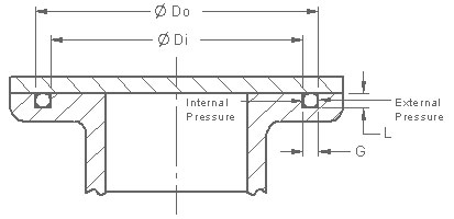
Gland Depth x Groove Width (area of the gland) must be larger than the cross section area of the o-ring. Otherwise many bad things will happen to your design.
|
L = Gland Depth L = Groove Depth + Clearance G = Groove Width G = (Do-Di)/2 |